0 items
No products in the cart.
For a light emitting diode (LED)to be operated successfully in it’s basic component form without any associated circuitry, it must be operated in constant current mode.
Because constant current techniques are relatively unfamiliar to most of us, many LED products are configured into a quasi or fully constant voltage mode by the use of surrounding circuitry.
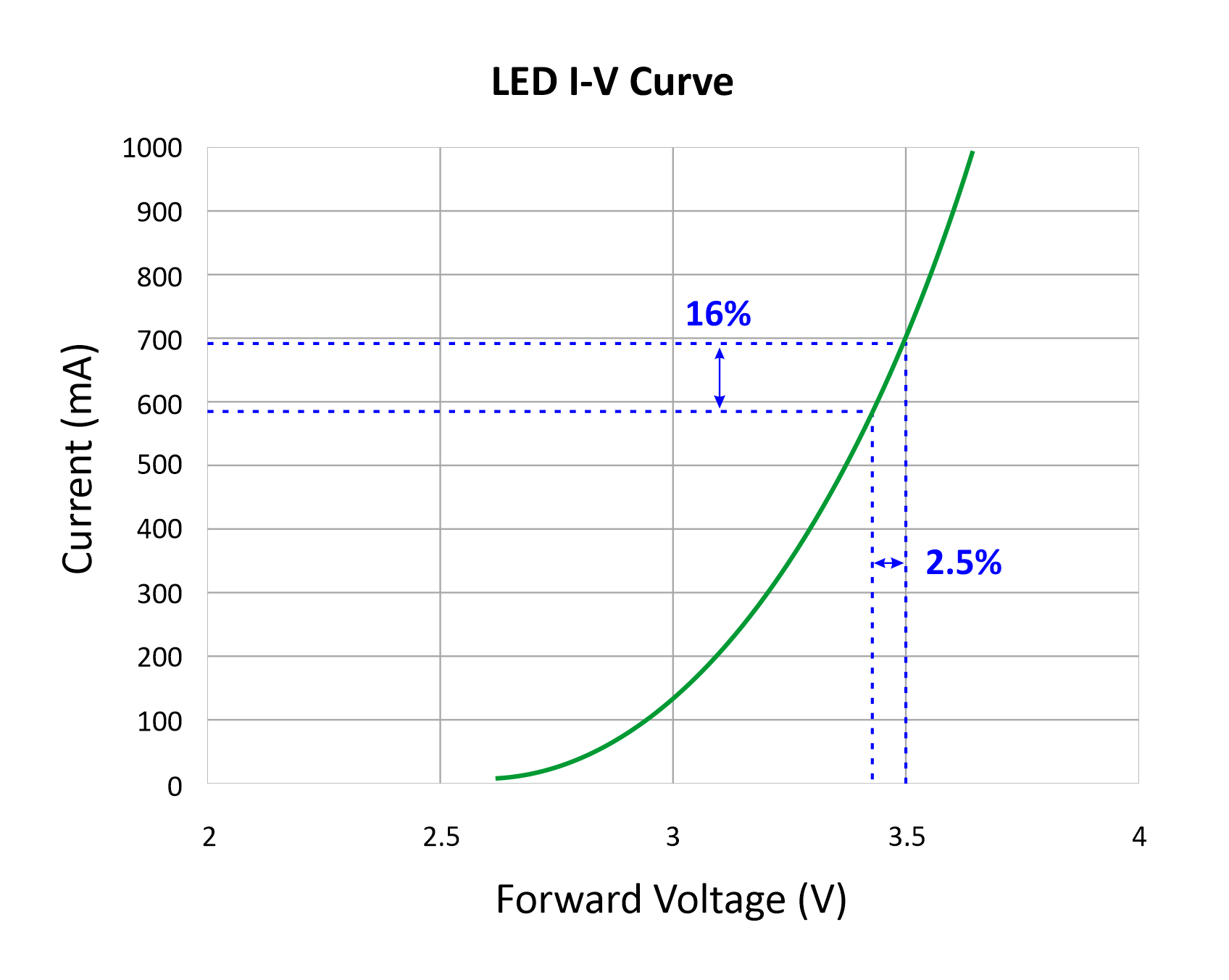
To understand why the LED component must be driven in constant current mode, look at the below graph showing forward current in milliamps vs forward voltage in volts for a typical white or blue LED. It shows that, in it’s typical operating zone, a small increase of forward voltage of 2.5% produces a much larger increase of 16% in forward current. Considering that the forward voltage of the LED is easily affected by temperature, this increase in current can be much larger than 16%.Higher temperature leads to higher current, leading to higher temperature and so on, til self destruction ultimately occurs. Consideration must also be given to the fact that this VI curve will vary markedly from batch to batch, and even within a batch. For these reasons, driving an LED component by constant voltage is fraught with danger.
Within any LED assembly driven from a constant voltage source, the LED components are ultimately driven in constant current mode. DC, of course.
The question poses : what are the pros and cons of both methods?
Let us consider a practical example where the finished LED fitting may be available in both constant current and constant voltage configurations. A simple one would be an installation of 1 watt deck lights in a floor or path. To view from the outside without disassembly, both lights look the same. However, the CC model has only an LED inside, whereas the CV model would also have either a series resistor or a tiny switchmode power supply ( SMPS ). For both models to light up to their design brightness, the CC model would likely have a current rating of 350mA, with a forward voltage drop of about 3V. The CV model would likely need 12V DC, and draw about 100mA (0.1A) (the built in SMPS acting like a dynamic “gearbox”).
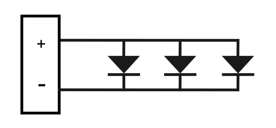
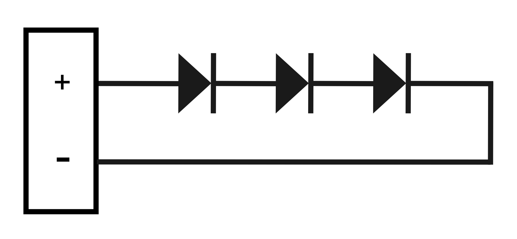
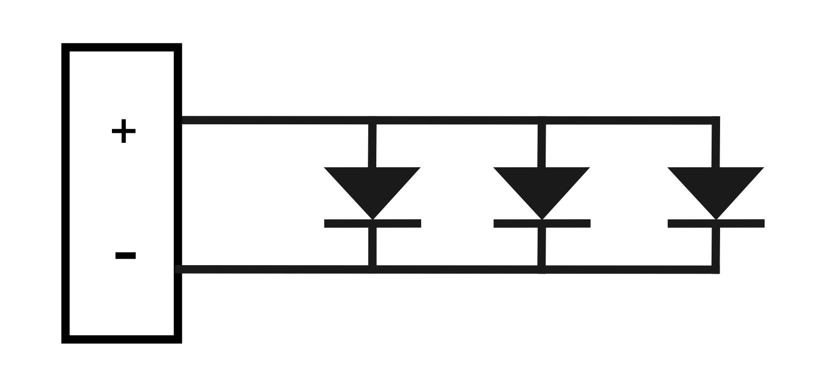
As you see, CC (series) involves running one wire from one light to the next in a daisy chain, and CV (parallel) requires running a negative and positive pair from one light to the next.
Let’s say there are 10 lights in the installation, and explore the constant current alternative. These lights may be slightly cheaper than the CV model, as there is no associated circuitry inside the fitting. If the CV model simply used a resistor, the cost premium of the CV would be negligible. If the CV model used a SMPS (which has other benefits as we will see shortly), then the extra cost of this CV model would be greater.
The CC model has a small improvement in reliability and lifetime, given that there is no electronics to age or fail.
The driver for this application would need to have a constant output of 350mA, at no less than 35V at 10 watts. A typical suitable driver found in a supplier’s catalogue might be rated at 350mA, output 25 – 40V at 15W. It is likely that a driver rated at 350mA, 40 – 50V, 20W would not work. Typically, the output voltage required must be within the voltage range specified on the driver.
Looking at the wiring, we now depart from tradition. The vast, vast majority of elements in the electrical world are connected in parallel, that is, the two supply wires both run from one load to the next (see circuit below). We need to change our thinking which now requires that a single wire connects from one side of the power supply to one side of the first LED. A single wire then runs from the other side of this first LED to the first side of the second LED, and so on in daisy chain fashion until the second side of the last LED connects back to the other side of the driver.
Be very aware, if there is ANY problem with any LED or any wiring or any connection, NO LED will work as the chain is broken. Troubleshooting can be tedious and time consuming, also taking into account that a multimeter may be of limited use because of the forward and reverse conduction of the LEDs (al la Christmas tree lights)!
When power is all on, ALL connections must be firm. No connection may be made or broken while power is switched on. The risk is very real that one or more of the LEDs may be destroyed!!
If the new LEDs in this CC installation are replacing an existing CV installation, and the wiring is not readily physically accessible, it may be a challenge to re-configure the existing wiring. Vice versa also applies.
Be aware that dimmable constant current drivers, using a variety of dimming techniques, are readily available.
An LED fitting designed for constant voltage is typically a basic LED, or series LED array, with either a resistor in series, or a SMPS to drive it.
To drive our installation of 10 x 1W LEDs, we need a power supply of 12V DC output at 1A or greater ( 0.1A x 10 ). All simple.
Negative and positive wires are taken from the driver to the first light, both continue to the second light, and so on. If any light is faulty, it is the only one which will not work. If any wiring is faulty, only lights on the remote side of the fault will not work. Fault finding is very simple!
A constant voltage decklight may use a series resistor, or a SMPS, to convert the LED element to CV operation. Each option has it’s pros and cons.
Using a series resistor is cheap and easy. Care must be taken to ensure that the nominal 12V input is not exceeded, or the life of the light will be reduced. Brightness will vary up or down as the supply voltage is increased and decreased. However, it is easily dimmable if required. Possibly not of significance, but it is also relatively inefficient, and more power may be wasted in the resistor than used to produce light!
A SMPS is a small PCB assembly using an IC, capacitor and inductor and a few support components. Above described as a “dynamic gearbox”, a 12V nominal input model may likely work well within the input voltage range of 8V to 30V, with no discernable difference in the LED brightness over this range. The input current varies inversely with the supply voltage, so that the input power ( volts x amps ) is fairly constant. At 8V the input current might be 150mA, and at 24V, around 50mA. So, a nominal 12V light is likely suited for 24V also.
A benefit of this is where the supply wiring may be long and suffer voltage drop at the far end. Even if it is down to 9V at this end, the light will be as bright as at the start of the chain.
However, because of this “dynamic gearbox” effect, it will resist dimming. Sometimes in practice, depending on the dimmer and the lamp, dimming can be satisfactorily achieved over some of the dimming range.
Sign up to our mailing list

Comments are closed.